VLAN configuration on OPNsense router, dd-wrt access points and TP-Link switches
Overview
I had a hard time getting my VLAN configuration to work, so I thought I’ll write down the process — maybe someone will find it useful.
My network configuration looks like this:
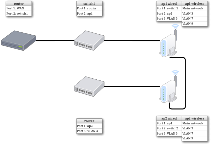
I have:
- A router (
router) running OPNsense on PCengines hardware; - Two access points (
ap1andap2) running dd-wrt on TP-Link WDR4300; - Two TP-Link Smart Easy switches (
switch1andswitch2) on TL-SE108E and TL-SE105E.
My goals:
- Three new Wi-Fi networks (one for guests, one for IoT devices, one for my own experiments);
- Port number 3 on ap1, ap2 and switch2 assigned to my own network exclusively;
- Ports number 1 and 2 pass VLAN tags all the way to the router, so the VLANs are visible to the OPNsense system.
Router configuration
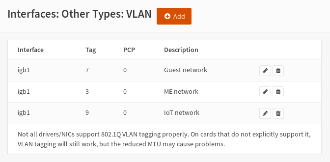
I started by configuring VLAN interfaces in OPNsense under
Interfaces > Other types > VLAN tab. I chose tag 3 for my private network, 7 for guest network and 9 for IoT network. All VLANs were created on a LAN interface (igb1 in my case).
Next, under Interfaces > Assignments I created new interfaces.
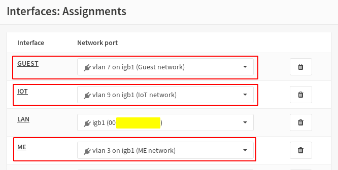
Configuration of the newly-created interfaces is described really well in OPNsense’s docs, so I am not going to repeat them (in my case I did skip configuring captive portal, vouchers and bandwidth limit — all I needed was to configure DHCP and firewall rules). You can find the guide here.
Switches configuration
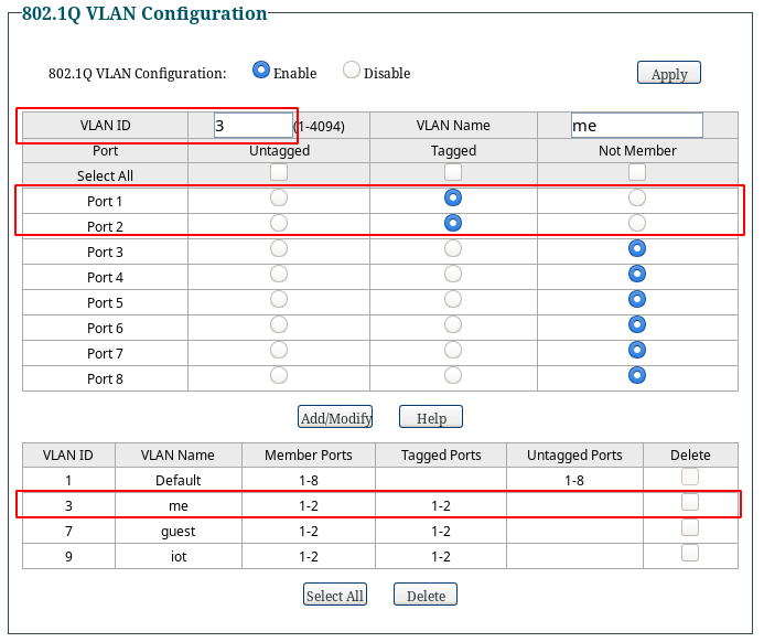
Next, I configured VLANs in switch1. Port based VLAN has to be disabled and 802.1Q VLAN has to be enabled. As router is connected to the first port in switch1 and ap1 is connected to the second port, I had to put ports 1 and 2 into all my VLANs as tagged ports. The rest of the ports are part of the default VLAN as untagged port. No device will be connected to any VLAN directly through switch1, we just need to pass VLAN packets between router and ap1.
Next, I configured switch2. This is the last device in my wired network, so the configuration for it varies a little from that of switch1. I just want to connect a single device to VLAN 3 using port 3, so switch2 does not need to have VLANs 7 and 9 configured — it does not pass any packets for these VLANs. So I created a single VLAN, with tagged ports 3 (to connect the device) and 1 (to pass down the packets all the way to the router through all other network devices).
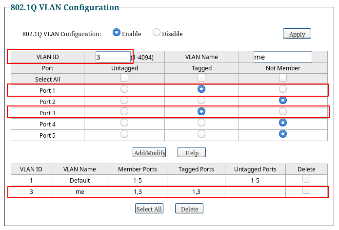
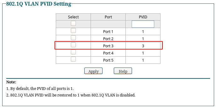
Because I want the device connected to port 3 to be available directly in VLAN 3, I had to configure port 3 to be in that VLAN by default. To do that, I set PVID for that port to the ID of the VLAN (3).
This didn’t allow me to test if my configuration was correct at that point, as I could not put any device into any of my VLANs by plugging it to router or switch1. I could only do that by using port 3 in switch2, but I hadn’t configured VLANs yet on ap1 and ap2 and they were in between.
Access points configuration
The dd-wrt configuration was the most complicated for me. Two things that I learned the hard way:
- TP-Link WDR4300 is an Atheros based router — it does not support configuring VLANs through
nvramcommand, you have to useswconfig; - Swconfig settings are not saved in nvram, so you have to run the
swconfigconfiguration with each boot; - There are a couple of naming schemes for VLAN devices, this is configured through
vconfigcommand, you can see your current configuration by usingcat /proc/net/vlan/config— tutorials use different schemes, so in your case it may bevlan3instead ofeth0.3— just check your current configuration and adapt the tutorial.
The main idea is quite simple: I created a new virtual WiFi interface working in Layer 2 (no IP address assigned to that interface), a new VLAN interface also working in Layer 2 with proper ports assigned to that VLAN and a bridge interface that bridged those two interfaces together, working in Layer 3 (IP address assigned to bridge interface).
First, I set up a new virtual interface under Wireless > Basic Settings. I made it unbridged. This created a new interface called ath0.1 with the following settings.
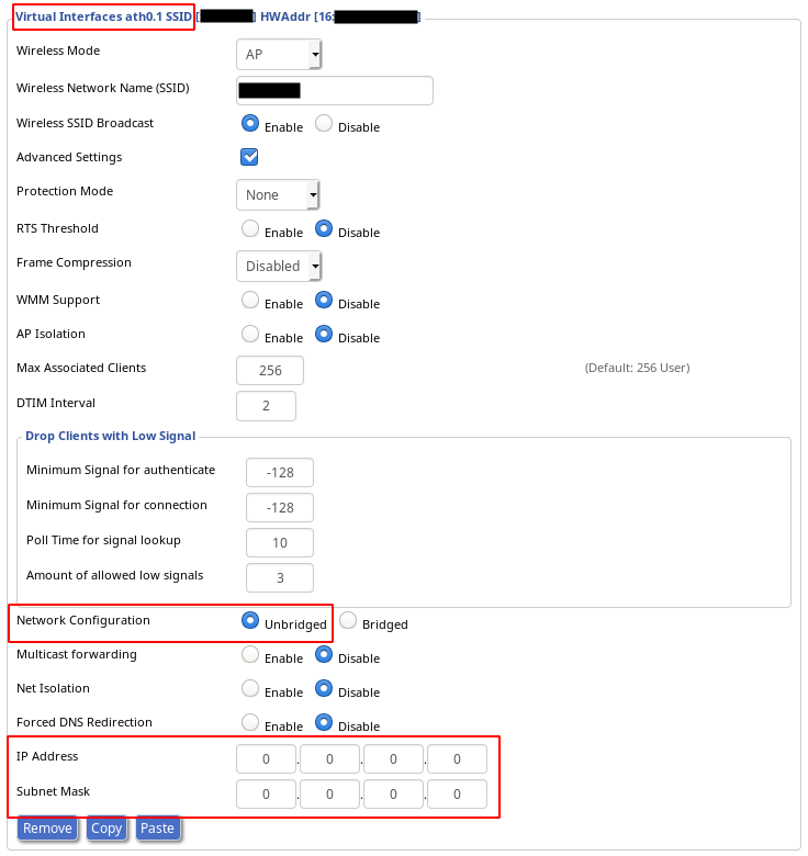
Two things:
- Remember to set up Wireless Security for you new WiFi network.
- If you want to use the second band WiFi, just set up a new virtual interface for it and just remember to assign it to a bridge later. I didn’t need it, so I just created a single virtual interface.
Next, under Setup > Networking I set up VLAN tagging. I created VLAN tags on eth0 interface.
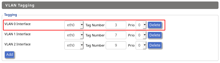
This created new interfaces with names that matched the vconfig scheme, so in my case it was eth0.3 for VLAN 3.
Then I configured the VLANs on the internal switch. This was the hardest part to get right. You can find the detailed description and a really helpful diagram in dd-wrt wiki here.
The switch has three physical interfaces — ath0 for 2.4GHz WiFi, ath1 for 5GHz WiFi, eth0 for physical connections and configuring the internal switch, all working in Layer 2, and three logical interfaces — vlan0 that represents LAN, vlan1 that represents WAN and br0 that represents whole LAN network and works in Layer 3 (it has an IP address). Normally, vlan1 also has an IP address of WAN, but in my case the dd-wrt works only as an access point, so there is no WAN, and vlan1 is assigned to br0 to get an extra LAN port.
It’s also important to get the port numbering right. WAN port has number 1, LAN ports have numbers 2 to 5, port 0 is the port that is physically connected to eth0 interface. Ports 0 and 2 to 5 are put to vlan0, ports 0 and 1 are put to vlan1.
I had to enable VLAN 3 on eth0 interface and assign ports to VLAN — just remember to mark the ports as tagged (ports 1 and 2 — or 2 and 3 when using the internal numbering scheme) or untagged (port 3 — or 4, by internal numbering scheme).
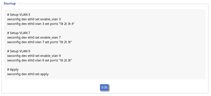
# Setup VLAN 3
swconfig dev eth0 set enable_vlan 3
swconfig dev eth0 vlan 3 set ports "0t 2t 3t 4"
For VLANs 7 and 9 I did not need a physical port, so I just set up tagged ports (note the lack of “4” at the end)
# Setup VLAN 7
swconfig dev eth0 set enable_vlan 7
swconfig dev eth0 vlan 7 set ports "0t 2t 3t"

# Setup VLAN 9
swconfig dev eth0 set enable_vlan 9
swconfig dev eth0 vlan 9 set ports "0t 2t 3t"
Then I just needed to apply the configuration
# Apply
swconfig dev eth0 set apply
This is not persisted in nvram, so I entered those commands in Administration > Commands and saved them as startup.
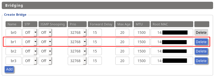
Then I had to configure bridges — the logical interfaces that would bridge together VLAN interface with WiFi virtual interface, and that would work in Layer 3 (with IP address assigned).
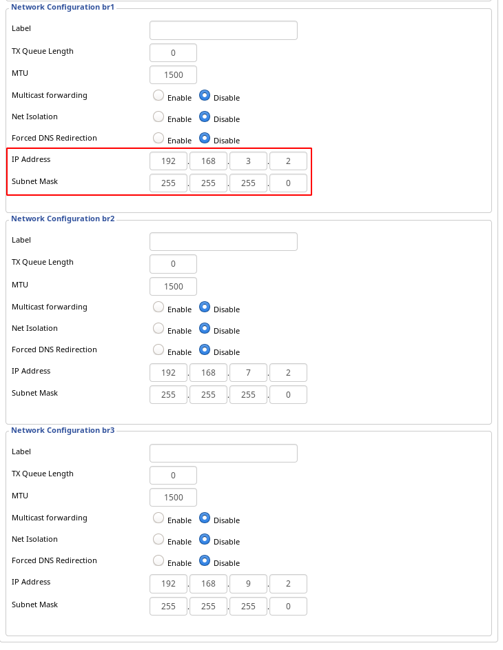
First, under Setup > Networking, I created three bridges, each for a single VLAN I was configuring.
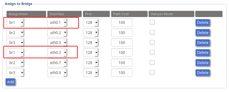
Then, I configured bridge assignments. For example, VLAN 3 is represented by bridge br1. I had to assign ath0.1 (WiFi virtual) and eth0.3 (VLAN) interfaces.
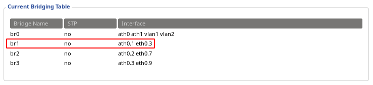
The full bridging table looks like this.
The last thing was to assign IP addresses to the bridges.
This was the last thing left to configure. I have all VLANs working now, just as I designed — I can connect to VLAN WiFi network or to a third port on ap1, ap2 or switch2 (only for VLAN 3).
And just a final word — I am no expert when it comes to networking, so if you find any errors, bad wording etc. — just email me and I’ll be more than happy to correct my mistakes.